Revit Modeling of the Cathedral of Brasilia
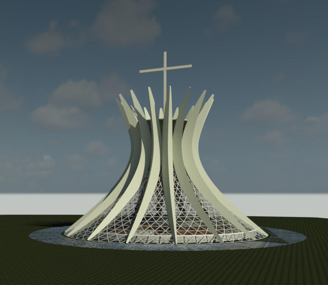 |
| Figure 1: The Cathedral Final Rendering |
Background Information
 |
| Figure 2: The Cathedral of Brasilia (http://catedral.org.br/historia) |
The Cathedral of Brasilia was designed by the architect Oscar Niemeyer and engineered by Joaquim Cardozo. An interesting fact is that this cathedral was officially the first monument created for Brasilia, which itself was finished being constructed in 1960. The cathedral consists of 16 hyperbolic concrete columns that encase an inner glass core. These columns allowed for the sanctuary of the Cathedral of Brasilia to exist without the use of interior column supports. The stained external glass of the structure was designed by Marianne Peretti in 1990.
 |
| Figure 3: Final Interior Rendering |
 |
| Figure 4: Triangular Curtain Panel |
Parametric Modeling Process
I stepped into this project without an initial vision of what to use for a parametric relationship in my design. In the early stages, I assumed that the relationship would have to involve the iconic concrete columns, which make the structure what it is. While modeling the columns, I discovered that the drafting process was much easier than I anticipated. This eventually led to me forming a parametric relationship between all the building components. I ultimately decided to base all dimension in the structure on one parameter, the structural height of the cathedral. This was achieved by building the structure at its approximate true height and creating ratios of the dimensional parameter with the overall height.
Parametric relationships
Curtain Panel
The original curtain panel design intent was to use a hexagonal pattern. Intersecting geometry arguments were the result of this shape, and the rendering of any adjustments took about 5-10 minutes to complete. I made the decision to simplify the design pattern by using the triangle, bent curtain panel as the foundation for my curtain panel. This decreased the overall time of rendering following adjustments, but at a grid of 20X60, the rendering still took about 2 -3 minutes.
Inscribed Triangle
Inscribed polygons were used to develop the overall shape of the columns. Placing a diameter parameter on the circle, which houses the triangle, ultimately allows the user to govern the thickness of the columns.
 |
| Figure 5: Inscribed Triangle |
The columns were then created with an overall height of about 131 feet using the inscribed triangles and multiple dots connected by a spline. These components combined to create the form for the columns. Figure 6 shows the column mass at approximately 131 feet, and figure 7 shows the column at 80 feet. Notice that all the column geometries are updated to keep the proper proportions throughout the entirety of the column.
 |
| Figure:6 Column Mass at Height Equal to 131 ft. |
 |
| Figure:7 Column Mass at Height Equal to 80 ft. |
Crosses
The cross that resides on the top of the Cathedral of Brasilia was also modeled as a conceptual mass with dimensions containing parametric relationships with the height. Figure 8 and Figure 9 show the cross mass at height of 31 ft. and 50 ft., respectively.
 |
| Figure 8: Cross Mass at Height Equal to 31 ft. |
 |
| Figure 9: Cross Mass at Height Equal to 50 ft. |
Complete Cathedral Family
All of the conceptual mass families were then brought together in the cathedral family. Figures 10 and 11 show the cathedral family at an overall height of 131 feet and 110 feet, respectively.
 |
| Figure 10: Cathedral at Height Equal to 131 ft. |
 |
| Figure 11: Cathedral at Height Equal to 150 ft. |
Dynamo Implementation
The second half of the project included the implementation of visual programming with the Dynamo software package. My initial design idea was to use the ability of Dynamo to automate a light switch. The idea was for the lights to automatically turn on at times of low light and automatically turn off during the daytime hours. This automation was to be based on the location of the sun in the sun settings within Revit. My intent was to reach a final product similar to figure 12 and 13.
 | ||||
Figure 12: Interior with light artificial sources and the sun
|


My secondary design idea was inspired by the transition lens eyeglasses that individuals wear. These transition lenses perform as regular reading lenses when inside of a building, but darken and effectively become sunglasses when individuals walk outside. I wanted to implement the same idea on my glass curtain panels. With this idea, the glass where the sun was directly shinning would become darker and not only better shade the occupants, but also lower air conditioning cost. The windows not being shinned on directly would exhibit a regular glass appearance.
I also ran into some major issues trying to implement this idea. The video examples we covered in class only changed the color of the surfaces in the current view. My intent was to physically change the color of the glass based on the position of the sun but was unable to successfully code a "physical" change that could be rendered. Figure 14 and 15 showcase the orientation of the panels to the sun and the tint that would be implemented in my design, respectively.
 |
| Figure 15: Panel Thermal Orientation with the Sun |
 |
| Figure 16: Panel Tint |
Comments
Post a Comment